

Si5351 DDS Clock Generator Using ATtiny13 Microcontroller with assembly language
Introduction
This is my project to demonstrate the simplicity of assembly language program. Usually we need lot of program size when we use Arduino compilers and its library. I’m much worried about the program size and coding efficiency. So i wanted to try my skill to make assembly language code to interface Si5351 DDS. After the introduction of mobile phones we lost our memory capacity to store the phone numbers in our brain. Similarly Arduino is spoiling our programming skills. It of-course opened up the creativity on hardware side, but on the software side most of the peoples copy-paste. The first place to look for Arduino code is google. Most of us just copy somebody’s library and use it. Arduino made everybody to hesitate to study the datasheet and follow the instruction. I’m not an anti-arduino man, but i want to say Arduino kills our coding capability.
The challenge in this project is 1kB or less program size to interface Si5351 chip. I took the challenge myself. In arduino 1kB is just enough to blink LED in some sequence. That’s the beauty of Arduino ..LOL
Project Specification:
- Use the Si5351 as variable frequency oscillator to cover CW range
- Ex : 7000 to 7050 KHz
- 10100 to 10150 KHz
- 14000 to 14050 KHz
- 3500 to 3550 KHz etc…
- To change the frequency using potentiometer
- CLK2 as beat frequency oscillator for required frequency
- Control the VFO or ON/OFF the CLK0 output with morse key
- 1 digital output for TX/RX relay
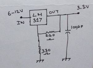
- Operating voltage is 3.3V for ATTiny13 and Si5351
Circuit Diagram

HEX Files :
80m – 3500 to 3550 KHz
40m – 7000 to 7050 KHz
30m – 10100 to 10150 KHz
20m – 14000 to 14050 KHz
Please contact me for source code. v u 3 x v r at the rate of gee mail dot com.
73
VU3XVR